
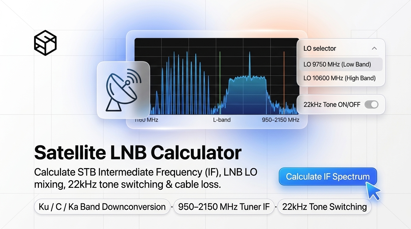
When setting up a satellite television dish, pointing a VSAT earth station terminal, or configuring a digital satellite set-top box (STB), technicians and telecommunications engineers are confronted with a fundamental paradox:
A satellite transponder transmits from geostationary orbit (35,786 kilometers in space) at microwave frequencies between 10.70 GHz and 12.75 GHz (Ku-band) or 3.40 GHz and 4.20 GHz (C-band). Yet when you open the receiver menu or connect a spectrum analyzer, the tuning frequency must be configured between 950 MHz and 2150 MHz (L-band).
If you type the satellite downlink frequency directly into your receiver, you get zero signal lock. Bridging this gap requires understanding the electromagnetic physics of the Low-Noise Block Downconverter (LNB), the mathematics of Superheterodyne Frequency Mixing, and the control protocols (13V/18V voltage switching and 22kHz tones) that govern satellite reception.
In this engineering manual, we provide the complete mathematical formulas for Ku-band and C-band downconversion, explain why high-frequency microwaves cannot travel through coaxial cable, dissect the internal circuitry of an LNB, and show you how to calculate exact receiver tuning parameters using the ShiftTools Satellite LNB Calculator.
Looking for an instant, private Satellite LNB Calculator?
Process, inspect, and export your files 100% locally in your browser memory with zero server uploads.
1. The Physics of Downconversion: Why Coaxial Cable Needs an LNB
Why can't we simply mount a passive antenna horn on a dish and run a copper cable directly into a satellite receiver?
The limitation is governed by dielectric skin depth and high-frequency RF attenuation. Standard RG-6 coaxial cable exhibits acceptable transmission losses at UHF and L-band frequencies (approximately 15 dB to 25 dB loss per 100 meters at 1 GHz).
However, at 12 GHz (Ku-band), attenuation in coaxial cable skyrockets to over 100 dB to 150 dB per 10 meters. If you ran 20 meters of coaxial cable directly from a passive 12 GHz feedhorn to a television receiver, the microscopic satellite signal (which arrives at Earth at approximately $-115\text{ dBm}$) would be completely obliterated by cable resistance before reaching the room.
The LNB solves this problem by performing two critical operations right at the focal point of the dish:
- Low-Noise Amplification: High Electron Mobility Transistors (HEMT) amplify the microvolt satellite signal by 50 dB to 65 dB with minimal added thermal noise (Noise Figure 0.1 dB to 0.3 dB).
- Block Downconversion: A local microwave oscillator mixes with the incoming signal, translating the entire block of microwave spectrum down into the friendly L-band (950 MHz to 2150 MHz), which easily travels through standard RG-6 cables.
2. The Mathematical Formulas: Local Oscillator (LO) Mixing
In a superheterodyne mixer, when two signals of frequencies $f_{RF}$ and $f_{LO}$ are combined in a non-linear diode or transistor, the output produces sum and difference frequencies:
The specific formula depends on whether you are tuning Ku-band Universal, Standard C-band, or Ka-band hardware:
A. Universal Ku-Band LNB (The Global Standard)
The total Ku-band downlink spectrum spans 2.05 GHz (from 10.70 GHz to 12.75 GHz). Because the receiver's L-band tuner window is only 1.20 GHz wide (950 MHz to 2150 MHz), the Ku-band is split into two sub-bands using two separate Local Oscillators:
| Ku Sub-Band | Downlink Range (fRF) | Local Oscillator (fLO) | Mathematical Formula | Receiver IF Output Range |
|---|---|---|---|---|
| Low Band | 10.70 GHz – 11.70 GHz | 9750 MHz (9.75 GHz) | IF = RF - 9750 |
950 MHz – 1950 MHz |
| High Band | 11.70 GHz – 12.75 GHz | 10600 MHz (10.60 GHz) | IF = RF - 10600 |
1100 MHz – 2150 MHz |
B. C-Band LNB (Spectral Inversion via High-Side Mixing)
Standard satellite C-band downlinks operate between 3.40 GHz and 4.20 GHz (3400 MHz to 4200 MHz). Standard C-band LNBs employ a high-side Local Oscillator of 5150 MHz:
Because the local oscillator is higher than the input radio frequency ($f_{LO} > f_{RF}$), spectral inversion occurs: a transponder at 3700 MHz outputs an IF of $5150 - 3700 = 1450\text{ MHz}$, while a transponder at 4100 MHz outputs a lower IF of $5150 - 4100 = 1050\text{ MHz}$.
3. Control Signals: 13V/18V Voltage and 22kHz Tone Switching
Because a single coaxial cable connects the set-top box to the roof-mounted LNB, the receiver must send control commands up the cable to tell the LNB which frequency band and polarization to receive:
| DC Voltage | 22kHz Tone | Selected Polarization | Selected LNB Band | Active Local Oscillator |
|---|---|---|---|---|
| 13V - 14V DC | OFF (0 Hz) | Vertical (RHCP in C-Band) | Ku Low Band | 9750 MHz |
| 18V - 19V DC | OFF (0 Hz) | Horizontal (LHCP in C-Band) | Ku Low Band | 9750 MHz |
| 13V - 14V DC | ON (22kHz, 0.6Vp-p) | Vertical (RHCP in C-Band) | Ku High Band | 10600 MHz |
| 18V - 19V DC | ON (22kHz, 0.6Vp-p) | Horizontal (LHCP in C-Band) | Ku High Band | 10600 MHz |
4. Real-World Calculation Walkthroughs
Let us calculate the exact intermediate frequencies for three real-world satellite broadcast transponders:
Example 1: BBC HD on Astra 28.2°E (Ku Low Band)
- Downlink Frequency ($f_{RF}$): 10,847 MHz ($10.847\text{ GHz}$), Vertical polarization.
- Band Selection: Since 10,847 MHz is below 11,700 MHz, this is Low Band. The 22kHz tone is set to OFF.
- Active LO: 9750 MHz.
- Calculation: $\text{IF} = 10,847 - 9750 = \mathbf{1097\text{ MHz}}$.
- Receiver Status: 1097 MHz falls cleanly within the 950–2150 MHz tuner window. The receiver supplies 13V with 0kHz tone.
Example 2: Sky Cinema on Astra 19.2°E (Ku High Band)
- Downlink Frequency ($f_{RF}$): 11,992 MHz ($11.992\text{ GHz}$), Horizontal polarization.
- Band Selection: Since 11,992 MHz exceeds 11,700 MHz, this is High Band. The 22kHz tone is set to ON.
- Active LO: 10600 MHz.
- Calculation: $\text{IF} = 11,992 - 10600 = \mathbf{1392\text{ MHz}}$.
- Receiver Status: The receiver supplies 18V with a continuous 22kHz tone.
Example 3: Free-to-Air News on C-Band (3840 MHz)
- Downlink Frequency ($f_{RF}$): 3,840 MHz, Horizontal polarization.
- Active LO: 5150 MHz.
- Calculation: $\text{IF} = 5150 - 3840 = \mathbf{1310\text{ MHz}}$.
- Receiver Status: Tuner locks at 1310 MHz with 18V supplied to the LNB.
5. Step-by-Step Guide: Calculating Frequencies with ShiftTools
-
Open ShiftTools Satellite LNB Calculator
Navigate to ShiftTools Satellite LNB Calculator. The tool runs locally in your browser with zero installation.
-
Select LNB Type
Choose Universal Ku-Band (9750/10600 MHz), Standard C-Band (5150 MHz), or input a custom local oscillator frequency.
-
Enter Downlink Transponder Frequency
Type the published satellite frequency in MHz (e.g. 11494 or 3840) and specify polarization (Horizontal or Vertical).
-
View Real-Time Telemetry & STB Configuration
The calculator instantly outputs the exact Intermediate Frequency (IF) in MHz, confirms tuner window passband validity (950–2150 MHz), displays required LNB voltage (13V vs 18V), and indicates the exact 22kHz tone state.
Frequently Asked Questions
Ready to use the Satellite LNB Calculator?
Use our free, private browser tool right now — 100% client-side with zero server uploads.